
It might look suspicious, but it’s just a clock.
I endeavored today to build some sort of clock with the materials we have in our maker lab at work. We do have a 2 line LCD display, but I thought a binary clock with LEDs would be cooler. That’s cooler in a nerd sort of way.
First, materials.
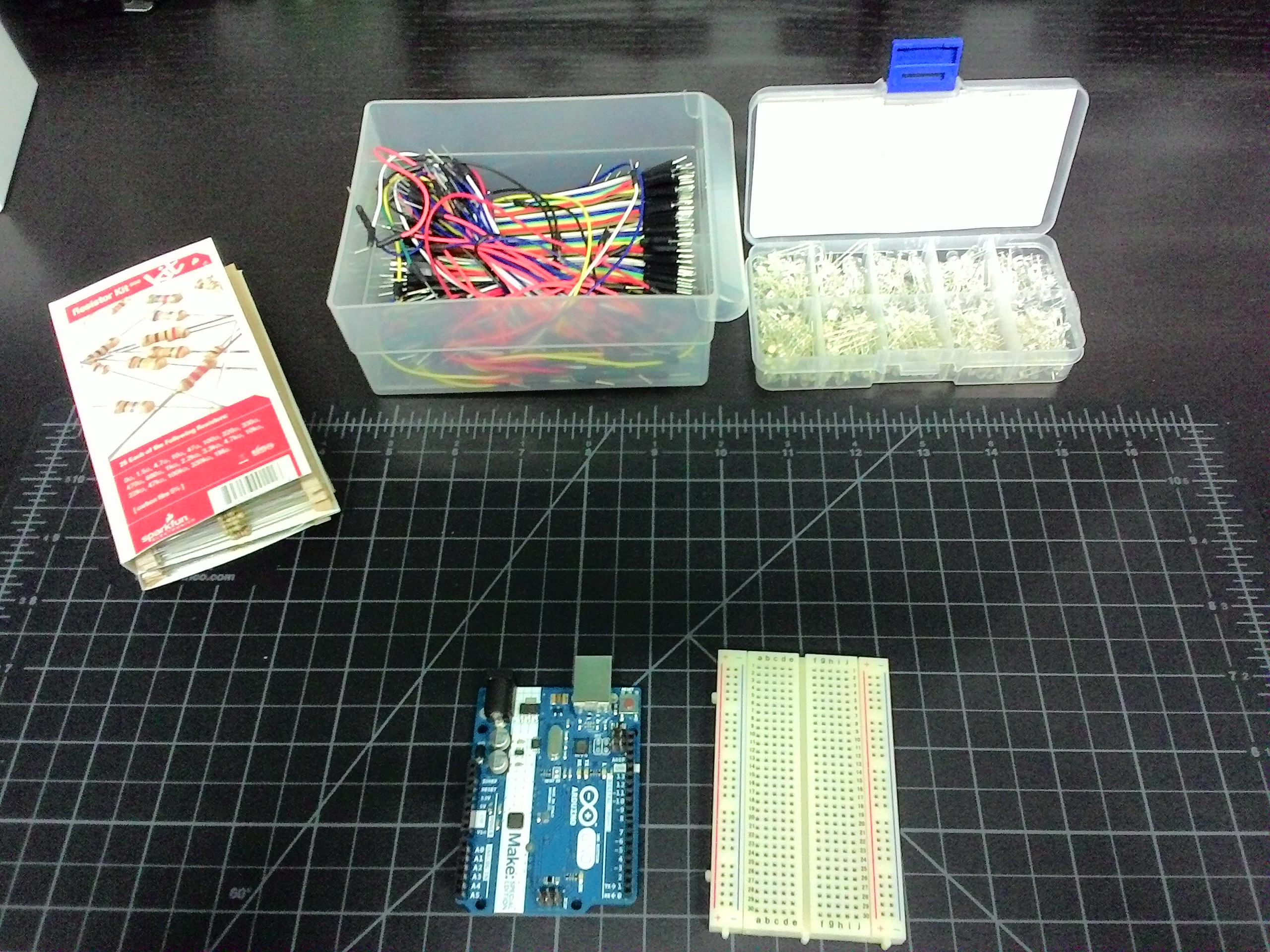
I started with an Arduino Uno, a standard size breadboard, a pack of resistors, wires, and LEDs. The resistors I’m going to be using are 330 ohm, and all the LEDs will be blue. I’ll try to group the wire colors logically, if I can, so that LEDs of a certain grouping are easily identifiable.
Let’s hook up one LED
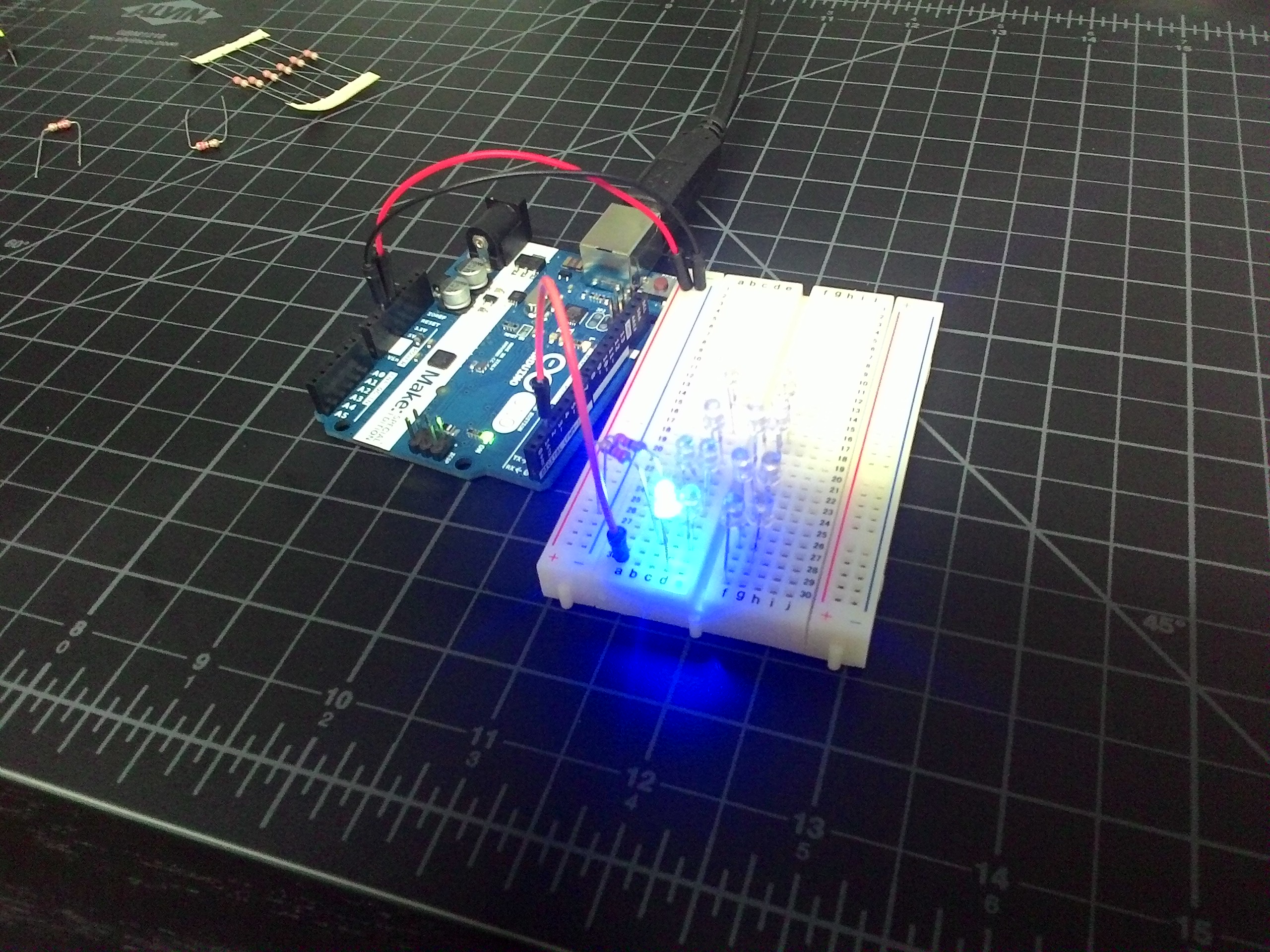 I was just playing with the Uno the day before, but these LEDs are new to me. I figured it’s probably good to start with a nice, basic layout to get warmed up. I used the example Blink sketch and changed it to the pin number I was using. I tried to get a picture with the LED on, and here it is.
Now, to focus on the LEDs
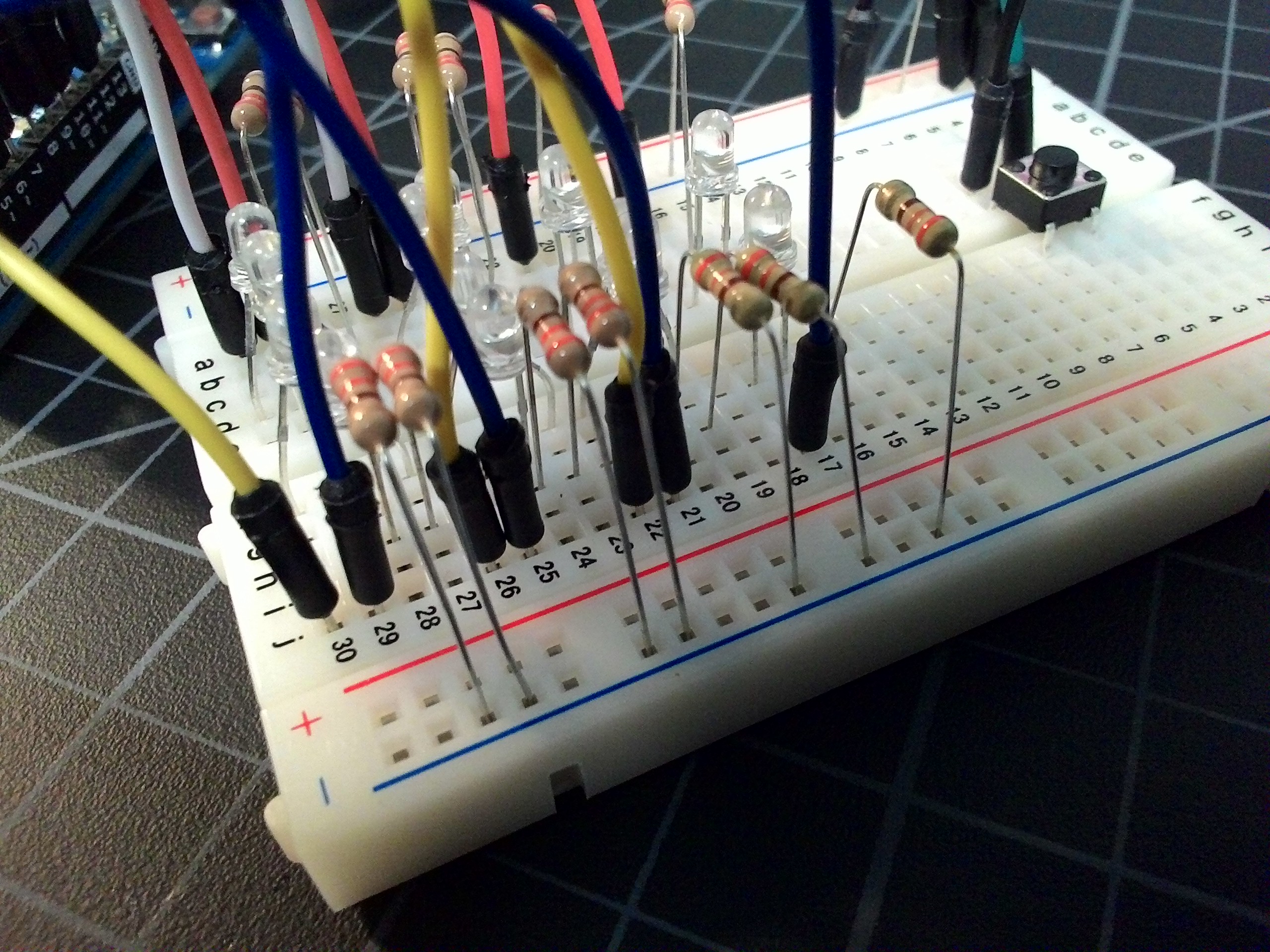
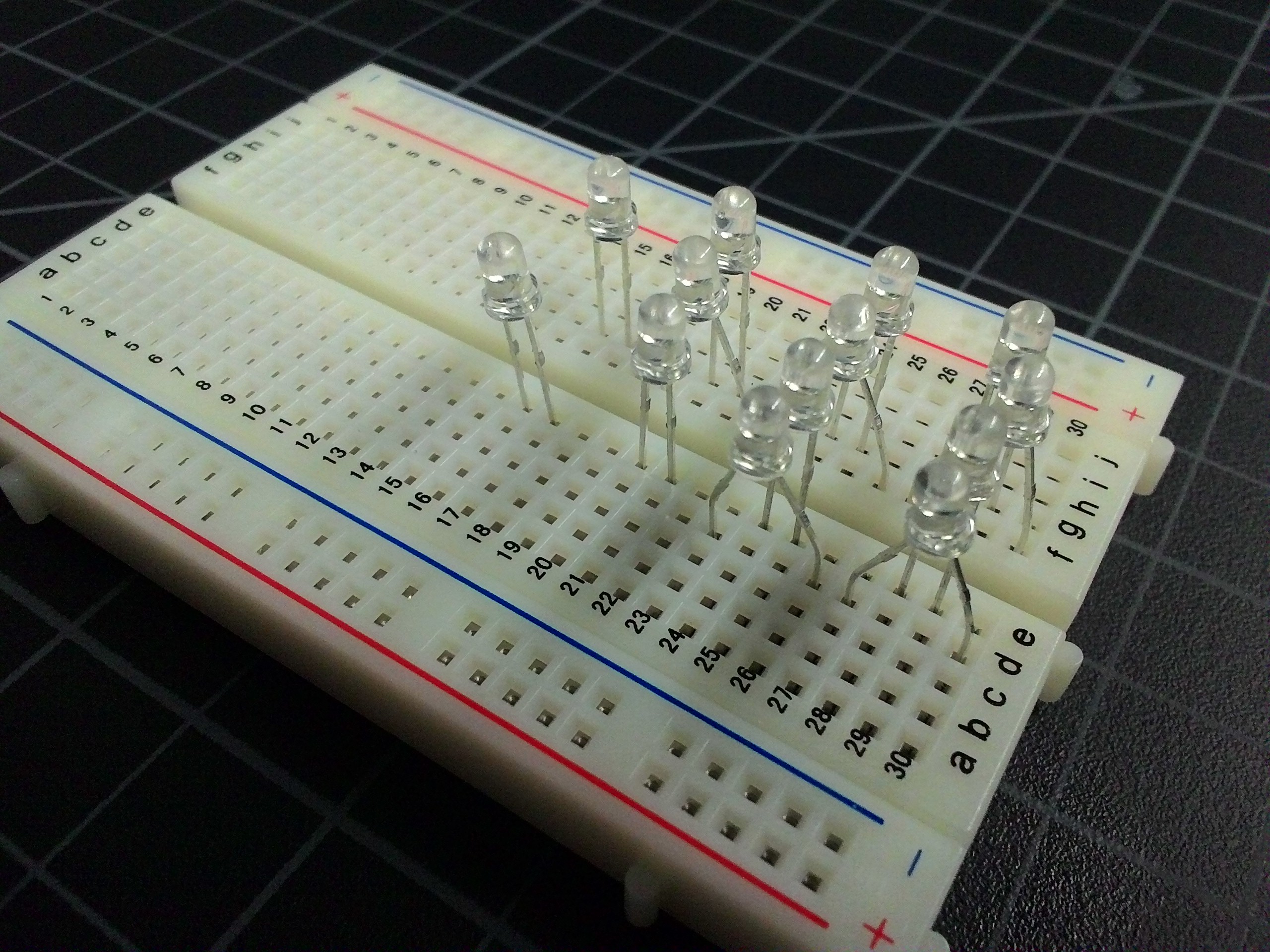 This is the board with just the LEDs in place. For the binary clock, I decided to use the more common layout with two columns of lights for each segment. That’s two columns for the hours, two for the minutes, and two for the seconds (which I’m not doing this time around). One column is the tens part, and one column is the ones part. That means 12:something would represent as 1 in the first hours column and 2 in the second.
In order to control the two columns independently in a breadboard, and space them logically, I placed the LEDs for the ones column in the board like normal. Then I made the LEDs for the tens column go in bow-legged. Click on the picture to zoom in and you’ll that the positive lead for the ten’s first light is in d30 and its negative lead is in d27. The positive lead for the one’s first light is in e29 and its negative lead is in e28. I used this same system for both the hours and minutes.
Wire up the hours
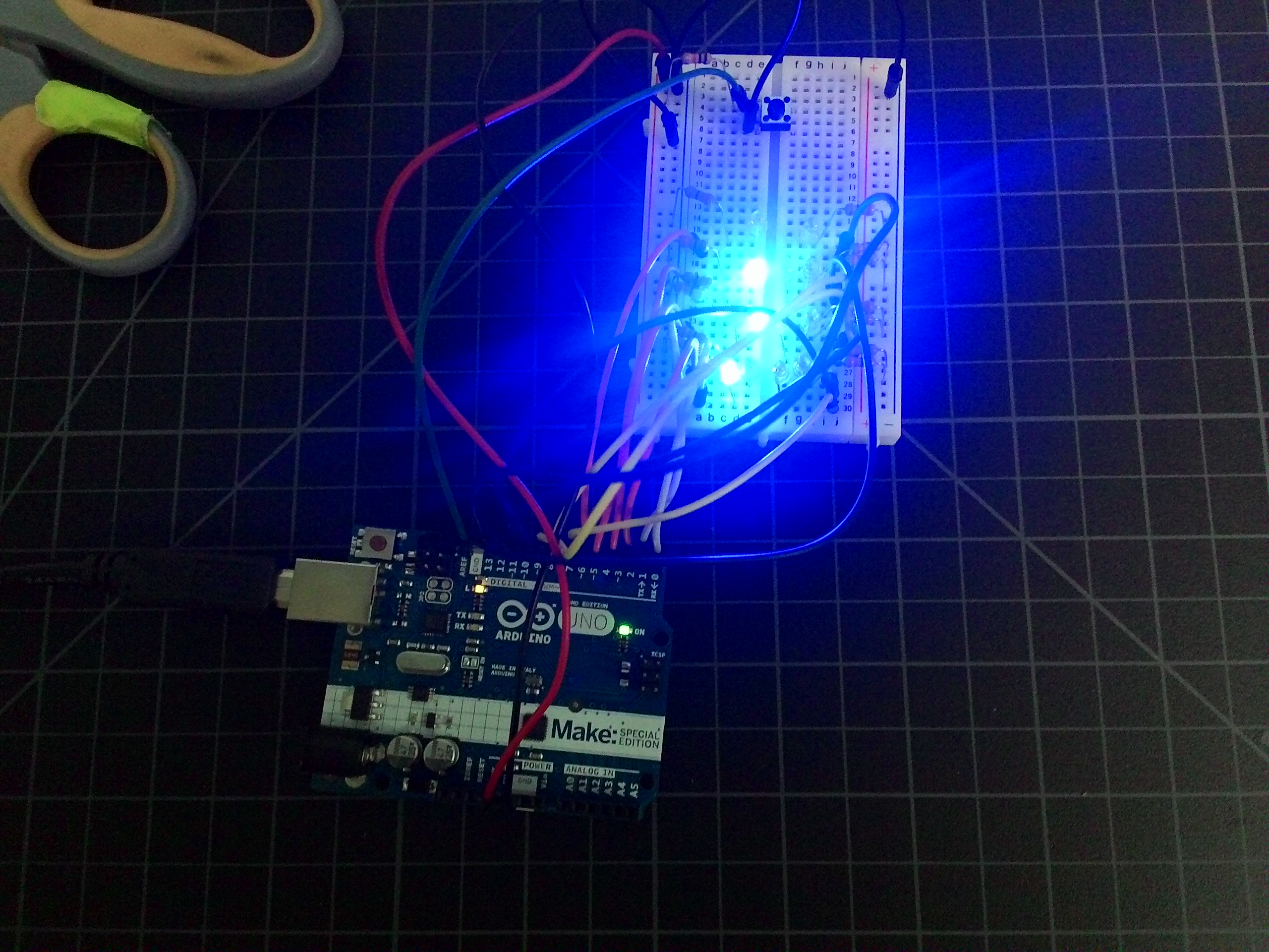
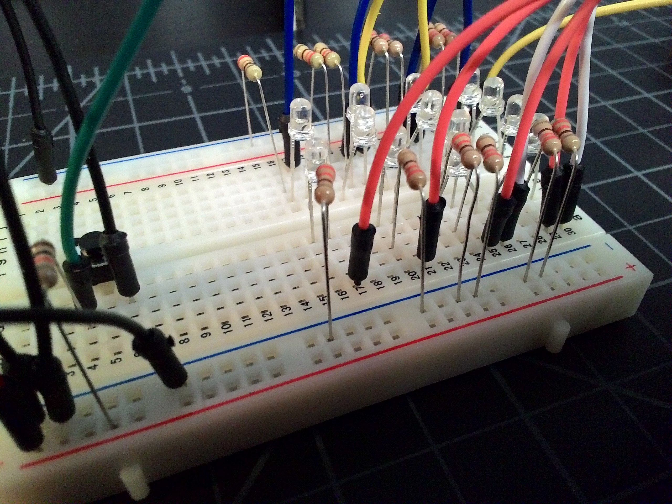 I know you can’t see the LEDs very well in this picture, but it’s the wires and resistors that are important. I need a wire from each digital output of the Arduino to go to the correct positive lead of the LED. I also need a 330 ohm resistor to go from the negative lead back to ground, so we don’t blow them.
This might not seem like the logical way to wire these up, but it will make more sense when we get to the code.
| Arduino Digital Output | Breadboard Grid Hole |
|---|---|
| 0 | a30 |
| 1 | a26 |
| 2 | a29 |
| 3 | a25 |
| 4 | a21 |
| 5 | a17 |
Then, remember to place resistors some where on 28, 27, 24, 23, 20, and 16 to the ground column.
Wire up the minutes
This feels familiar. We’re gonna do the same thing here we just did.
| Arduino Digital Output | Breadboard Grid Hole |
|---|---|
| 6 | j30 |
| 7 | j26 |
| 8 | j22 |
| 9 | j29 |
| 10 | j25 |
| 11 | j21 |
| 12 | j17 |
Remember resistors for all the negative leads.
Turns out I need a button to set the time.
 My plan was to set the time by sending a message over the serial cable, like it does in the time library examples. However, when I turned Serial on, the Arduino would hijack pins 0 an 1 for communication. I don’t have enough room to move off those pins, so I needed a different plan. I figured I would start the clock at 8:00 and then let someone set the time by adding minutes with a button press. You can see the button here near the top of the board.
A 10,000 ohm resistor goes from the positive power channel to c4. Then a wire goes from d4 to digital pin 13 on the Ardrino. The switch sits in rows 4 and 6. Finally, a wire goes from d6 to the ground on the breadboard.
All done, but the coding.
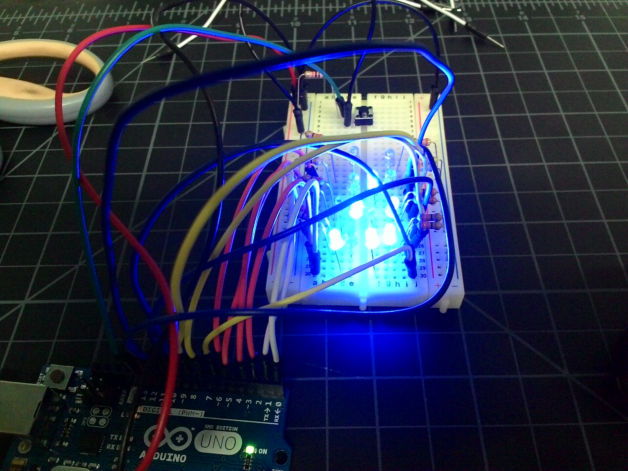
Here’s a finished image of the clock indicating that the time is 12:53.
Now for the code. Here’s the whole sketch.
#include <Time.h>

int waitCounter = 0;

void setup() {
  // put your setup code here, to run once:
  int i = 0;
  // pins 0 through 12 are LEDs
  for (; i < 13; i++)
  {
    pinMode(i, OUTPUT);
  }
  pinMode(13, INPUT);
  // Do a little startup animation
  for (i = 0; i < 13; i++)
  {
    animateLights(i);
    delay(250);
  }
  digitalWrite(12, LOW);
  // Set the start time to 8:00 AM
  setTime(8 * 60 * 60);
}

void loop() {
  // if the button is pressed, advance 1 minute
  if (digitalRead(13) == 0)
  {
    adjustTime(60);
  }
  // get the time and show it
  int theHour = hour();
  int theMinute = minute();
  showHours(theHour);
  showMinutes(theMinute);
  // take a breath
  delay(100);
}

void showHours(int theHour)
{
  int tens = theHour / 10;
  digitalWrite(0, ((tens >> 0) & 1) ? HIGH : LOW);
  digitalWrite(1, ((tens >> 1) & 1) ? HIGH : LOW);
  int ones = theHour % 10;
  digitalWrite(2, ((ones >> 0) & 1) ? HIGH : LOW);
  digitalWrite(3, ((ones >> 1) & 1) ? HIGH : LOW);
  digitalWrite(4, ((ones >> 2) & 1) ? HIGH : LOW);
  digitalWrite(5, ((ones >> 3) & 1) ? HIGH : LOW);
}

void showMinutes(int theMinute) {
  int tens = theMinute / 10;
  digitalWrite(6, ((tens >> 0) & 1) ? HIGH : LOW);
  digitalWrite(7, ((tens >> 1) & 1) ? HIGH : LOW);
  digitalWrite(8, ((tens >> 2) & 1) ? HIGH : LOW);
  int ones = theMinute % 10;
  digitalWrite(9, ((ones >> 0) & 1) ? HIGH : LOW);
  digitalWrite(10, ((ones >> 1) & 1) ? HIGH : LOW);
  digitalWrite(11, ((ones >> 2) & 1) ? HIGH : LOW);
  digitalWrite(12, ((ones >> 3) & 1) ? HIGH : LOW);
}

void animateLights(int light) {
  if (light == 0)
  {
    digitalWrite(0, HIGH);
    digitalWrite(12, LOW);
  }
  else
  {
    digitalWrite(light, HIGH);
    digitalWrite(light - 1, LOW);
  }
}
and that’s almost all of it.
Share the fun
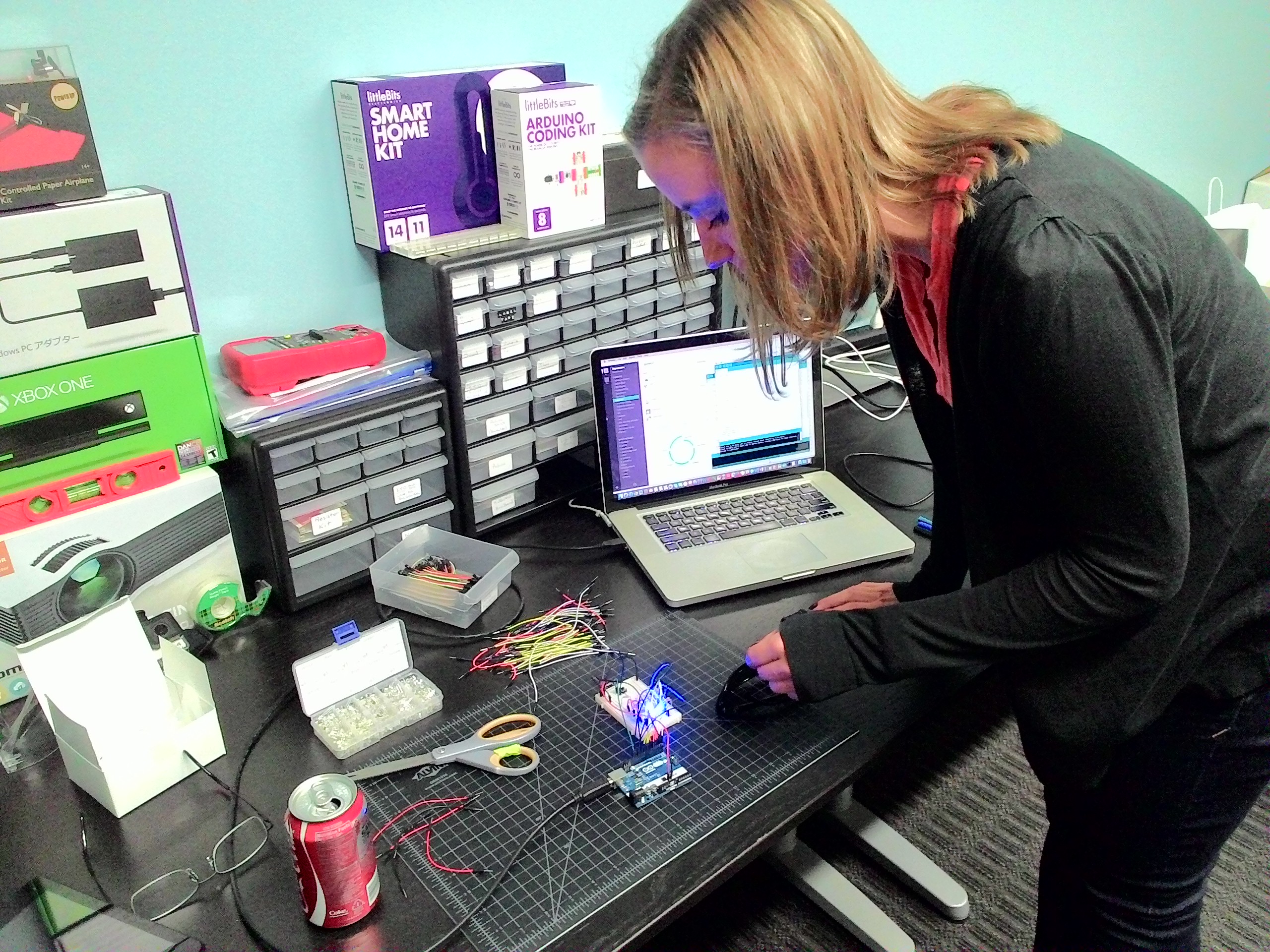 In the spirit of this project (many people made clocks this week), I was supposed to share the experience with a non-technical person. This is Jill, our HR manager (along with a billion other hats), learning about binary clocks, Arduinos, and LEDs.
By the way, Jill (and Amber who isn’t pictured here) have a great blog on Denver restaurants called Savor Mile High. Check it out Jill’s and Amber’s Foodie Blog.
I’ll probably expand on this project over time. I’d like a pair of columns for seconds. I’d like to house the entire thing in something that shows the workings but arranges the LEDs more artistically. Maybe I’ll make it into a kit.
